Low-Voltage Driver PCB for Four PEM-Electrolyzer BCDs
A custom PCB designed to operate four low-voltage PEM-electrolyzer buoyancy control devices and interface with four depth sensors for underwater robot depth and orientation control experiments.
Low-Voltage Driver PCB for Four PEM-Electrolyzer BCDs
This project was a custom electronics board designed for an underwater robotics experiment using four PEM-electrolyzer-based buoyancy control devices, or BCDs. The goal of the PCB was to provide a compact, reliable, and organized way to operate four low-voltage electrochemical buoyancy modules while also supporting distributed depth sensing on the robot.
The board was developed as supporting hardware for a broader research direction in buoyancy-based underwater robot control. In this approach, an underwater robot changes its buoyancy by controlling gas generation through proton exchange membrane, or PEM, electrolysis. When multiple BCDs are placed around the robot body, the system can influence not only vertical motion but also orientation, including pitch and roll.
My contribution in this specific project was the electronics integration: designing a PCB that could drive four low-voltage PEM-electrolyzer channels and provide clean sensor connections for experimental testing.
Research Context
This PCB connects to the buoyancy-control research direction developed through the Bio-inspired Robotics and Control Lab at the University of Houston and collaborators at Rice University. The related research has involved Dr. Zheng Chen, Prof. Fathi H. Ghorbel, Denizcan Koc, Qiang Zhu, and earlier contributors such as Dr. Alicia Keow and Dr. Wenyu Zuo.
The core idea behind this research is that underwater robots do not always need to rely only on thrusters, pumps, or propellers to change depth. In papers such as “Buoyancy Control Device Enabled by Reversible PEM Fuel Cells for Fine Depth Control”, “Reversible Fuel Cell Enabled Underwater Buoyancy Control”, and “Energy Efficient Depth Control for Underwater Devices Using Soft and Hard Actuators”, the researchers explored how reversible fuel cells and PEM electrolysis can be used to generate or consume gas, changing the displaced volume of the system and therefore changing buoyancy.
More recently, Denizcan Koc, Qiang Zhu, Prof. Fathi H. Ghorbel, and Dr. Zheng Chen extended this direction toward experimental validation of underwater depth and orientation control using reversible fuel-cell electrolysis in “Experimental Validation of Underwater Depth and Orientation Control Using Reversible Fuel Cell Electrolysis”. That work is especially relevant to this PCB because it involves distributed buoyancy-control devices for controlling both depth and orientation.
Image credit: Jeff Fitlow/Rice University, via Rice News. The Rice News article describes a fuel-cell/BCD underwater robot prototype related to the UH-Rice buoyancy-control research collaboration.
A useful way to understand the concept is this: instead of continuously using thrusters to push the robot up or down, the robot can change its buoyancy by generating gas. If the gas-generation modules are distributed around the vehicle, the robot can create different buoyancy forces at different locations. That makes it possible to study depth control, pitch control, roll control, and hybrid control strategies that combine conventional thrusters with soft buoyancy-based actuation.
Why a Custom PCB Was Needed
The experimental system required four PEM-electrolyzer BCD channels. Each BCD needed to be controlled independently so the robot could activate different buoyancy modules depending on the desired depth or orientation correction.
A breadboard or loose wiring setup would not be reliable enough for repeated underwater robotics experiments. The system needed a cleaner electrical interface with labeled channels, proper connectors, and a layout that matched the physical arrangement of the BCDs on the robot.
The PCB was designed to support:
- Four independently controlled PEM-electrolyzer BCD channels
- Low-voltage operation around 3 V
- Four depth sensor connectors
- ESP32-based embedded control
- Screw-terminal connections for the electrolyzer outputs
- A layout that directly maps to the robot's physical BCD locations
- Easier debugging, testing, and integration with the underwater platform
The University of Houston Subsea Systems Institute project page on bio-inspired buoyancy control for subsea service AUVs describes the larger system-level goal: integrating BCDs with an underwater service robot and developing depth and orientation control using both hard and soft actuators. This PCB was a practical electronics step toward making that kind of multi-BCD experimental system easier to operate.
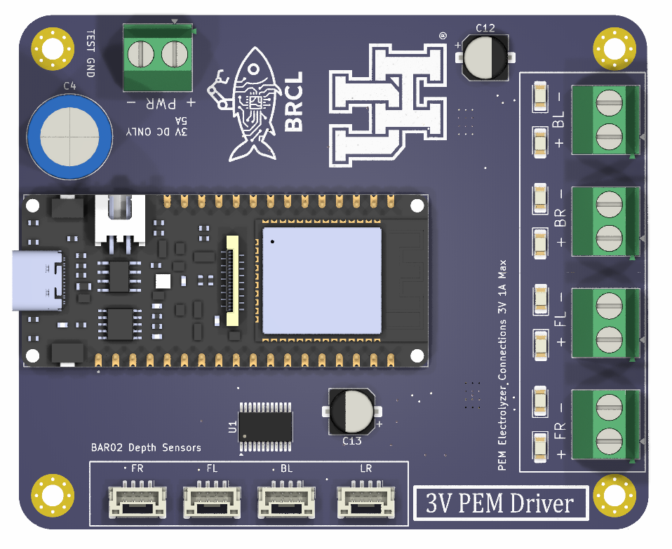
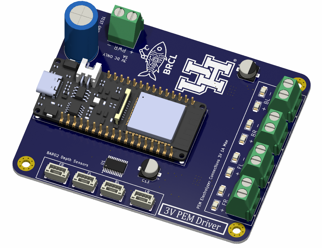
Hardware Layout
The board includes four main electrolyzer output channels:
- FR — front-right BCD
- FL — front-left BCD
- BL — back-left BCD
- BR — back-right BCD
This physical labeling was important because the electronics had to correspond clearly to the robot geometry. For example, if a controller commands the front-right BCD, the wiring should make it obvious which actuator is being energized.
The board also includes connectors for four BAR02 depth sensors. These sensors allow the robot to collect depth or pressure feedback from multiple locations. Distributed sensing is useful when the system is being tested for depth and orientation behavior because it provides more information than a single pressure measurement.
At the center of the board is an ESP32 development module, which provides the embedded control interface. The ESP32 can command the driver channels, communicate with sensors, and act as the main electronics interface for testing the BCD system.
Design Challenge: Driving a 3 V Electrochemical Load
One of the main challenges in this project was the low operating voltage of the PEM electrolyzer modules. Since the BCDs operate at approximately 3 V, driver selection was not straightforward.
Many common driver boards and switching circuits are easier to use with higher-voltage loads. At low voltage, even a small voltage drop across the driver can become significant. The driver therefore had to be selected carefully so that the electrolyzer modules could be powered reliably while still being controlled from ESP32 logic-level signals.
The design had to consider:
- Low-voltage switching performance
- ESP32 logic compatibility
- Independent channel control
- Current handling for the electrochemical load
- Simple wiring during experiments
- Safe and repeatable testing in a lab environment
This made the PCB more than just an adapter board. It was an integration board combining low-voltage power electronics, embedded control, and sensor interfaces for underwater robotics experiments.
Application: Four-BCD Orientation Control
The main application of the PCB was to support underwater robot orientation-control experiments using four distributed buoyancy modules.
With one BCD, a robot can mainly affect its vertical buoyancy. With multiple BCDs placed around the body, the system can create a buoyancy distribution. That distribution can generate attitude effects. For example:
- Activating front BCDs differently from rear BCDs can influence pitch.
- Activating left and right BCDs differently can influence roll.
- Activating all BCDs together can influence depth.
- Combining BCD actuation with thrusters can create a hybrid hard/soft actuation system.
This is why the four-channel PCB was important. It provided the hardware layer needed to test more advanced control ideas where each buoyancy module could be treated as an independent actuator.
The public Rice News feature on the BayMax/Monarch underwater robot gives a good visual example of this broader concept. The article describes a remotely operated underwater robot that uses water-splitting fuel cells for buoyancy control and connects the project to the collaborative research involving Prof. Ghorbel's group at Rice and Dr. Zheng Chen's lab at the University of Houston.

Image credit: Jeff Fitlow/Rice University, via Rice News image downloads. This public image is included as contextual background for the broader fuel-cell/BCD underwater robotics work, not as an image of my PCB.
My Contribution
My contribution was focused on the PCB and electronics side of the system. The main task was to convert the four-BCD experimental concept into a clean and practical hardware interface.
This included:
- Designing the PCB layout
- Organizing four independently controlled BCD channels
- Selecting a suitable low-voltage driver approach for the approximately 3 V electrolyzer loads
- Providing connectors for four depth sensors
- Integrating the control interface around an ESP32 development board
- Labeling the actuator outputs according to the robot's physical BCD arrangement
- Making the system easier to wire, test, and debug during experiments
The board helped reduce wiring complexity and made the experimental system more repeatable. Instead of rebuilding the wiring for every test, the robot could use a dedicated interface board designed specifically for the four-BCD configuration.
Skills and Tools Used
- PCB design and layout
- Low-voltage driver selection
- Embedded electronics integration
- ESP32-based control hardware
- Underwater robotics hardware integration
- Sensor interface planning
- PEM-electrolyzer BCD support
- Experimental robotics prototyping
Outcome
The final PCB provided a compact control and integration platform for four PEM-electrolyzer BCD modules and four depth sensors. It supported the experimental goal of using distributed buoyancy actuation for underwater robot depth and orientation control.
Although this board was a small part of a larger research effort, it solved a very practical engineering problem: how to reliably connect, drive, and test four low-voltage electrochemical buoyancy modules in a robotics experiment.
For me, this project was a good example of how robotics research depends not only on control theory and modeling, but also on careful hardware integration. A research idea becomes testable only when the electronics, sensors, drivers, and physical wiring are reliable enough to support repeated experiments.