Everything You Need to Know About Electronics
Workshop Notes for Mechanical, Robotics, and Non-Electrical Engineers
Electronics often looks more complicated than it actually is.
For many mechanical engineers, robotics engineers, manufacturing engineers, and students from non-electrical backgrounds, electronics feels unfamiliar because the behavior is not always visible. In mechanical systems, you can often see motion, force, vibration, deformation, or failure. In electronics, voltage and current are usually invisible. A circuit may look perfectly fine, but one wrong connection, one missing ground, or one incorrectly selected component can stop the whole system from working.
Note: Voltage is like electrical pressure. It causes current to flow when there is a complete path.
The goal of this workshop is not to turn you into an electrical engineer.
The goal is to give you enough practical understanding so that basic circuits, schematics, and PCB designs start making sense.
If you are working with robots, machines, sensors, control systems, embedded devices, or any electromechanical product, you will eventually come across electronics in some form. You may not need to design every circuit from scratch, but having a basic understanding of electronics makes a big difference. It helps you read datasheets, recognize common components, understand schematics, follow PCB designs, and communicate more confidently with electrical engineers.
The purpose of this workshop is to build that working knowledge. The goal is not to make electronics look difficult, but to make it feel approachable. After learning a few basic ideas, many circuits that initially look confusing start to make sense.
In this first part, we will connect basic electronics with mechanical system concepts that you may already understand.
One of the best ways to understand electronics is to compare an electrical circuit with a mechanical mass-spring-damper system.
A basic electrical RLC circuit has:
- resistor
R - inductor
L - capacitor
C - voltage
V - current
I
A basic mechanical system has:
- damper
b - mass
m - spring
k - force
F - velocity
v - displacement
x
These two systems behave in very similar mathematical ways.
| Electrical System | Symbol | Mechanical System | Symbol | Meaning of the Analogy |
|---|---|---|---|---|
| Voltage | V |
Force | F |
Voltage is the driving effort in an electrical system, just like force is the driving effort in a mechanical system. |
| Current | I |
Velocity | v |
Current is the rate of flow of charge, similar to velocity being the rate of change of position. |
| Charge | q |
Displacement | x |
Charge is the accumulated effect of current, just like displacement is the accumulated effect of velocity. |
| Resistor | R |
Damper | b |
A resistor dissipates electrical energy as heat, similar to how a damper dissipates mechanical energy. |
| Inductor | L |
Mass | m |
An inductor resists sudden changes in current, similar to how mass resists sudden changes in velocity. |
| Capacitor | C |
Spring compliance | 1/k |
A capacitor stores electrical energy, similar to how a spring stores mechanical energy. In this analogy, capacitance behaves like mechanical compliance, which is the inverse of stiffness. |
| Inverse capacitance | 1/C |
Spring stiffness | k |
A smaller capacitor behaves like a stiffer spring because it produces a larger voltage for the same stored charge. |
For a mechanical mass-spring-damper system, the force equation is:
For a series RLC electrical circuit, the voltage equation is:
Since current is the rate of change of charge,
and velocity is the rate of change of displacement,
the analogy becomes very clear:
| Mechanical Equation Term | Electrical Equation Term | Interpretation |
|---|---|---|
m dv/dt |
L dI/dt |
Inertia effect: resistance to sudden change |
bv |
RI |
Damping/resistive loss |
kx |
(1/C)q |
Stored energy effect |
F |
V |
External driving input |
So, in simple words:
- an inductor behaves like a mass
- a resistor behaves like a damper
- a capacitor behaves like a spring/compliance
- voltage behaves like force
- current behaves like velocity
- charge behaves like displacement
This is why electrical circuits and mechanical systems often have similar responses.
For example:
- A mass resists sudden change in velocity.
- An inductor resists sudden change in current.
Similarly:
- A spring stores mechanical energy.
- A capacitor stores electrical energy.
And:
- A damper dissipates mechanical energy.
- A resistor dissipates electrical energy.
This analogy is very useful because it shows that electronics is not a completely different world. Many electrical systems follow the same kind of dynamic behavior that mechanical engineers already study in vibrations, controls, and system modeling.
The discussion will stay practical. We will avoid unnecessary theory and focus on the concepts that are directly useful when building or designing real systems.
By the end of this section, you should be able to look at a simple circuit and understand what each part is doing.
Equivalent Components: From Springs to Resistors
Before talking about resistors, let us start with a familiar mechanical question.
Answer This
If two identical springs, each with stiffness K, are connected in parallel, what is the equivalent stiffness?
Click to see the answer
When two identical springs are connected in parallel, both springs experience the same displacement, but the total force is shared between them.
For one spring:
For two springs in parallel:
So the equivalent stiffness is:
Two identical springs in parallel behave like one spring with double the stiffness.
This idea is very common in engineering: when multiple elements are connected together, we often replace them with one equivalent element.
For example:
- multiple springs can be replaced by an equivalent spring
- multiple dampers can be replaced by an equivalent damper
- multiple resistors can be replaced by an equivalent resistor
The same type of thinking is used in electronics.
Instead of asking, “What is the equivalent stiffness?”, we ask:
What is the equivalent resistance?
Resistors in Series
Two resistors are in series when they are connected one after another, so the same current flows through both of them.
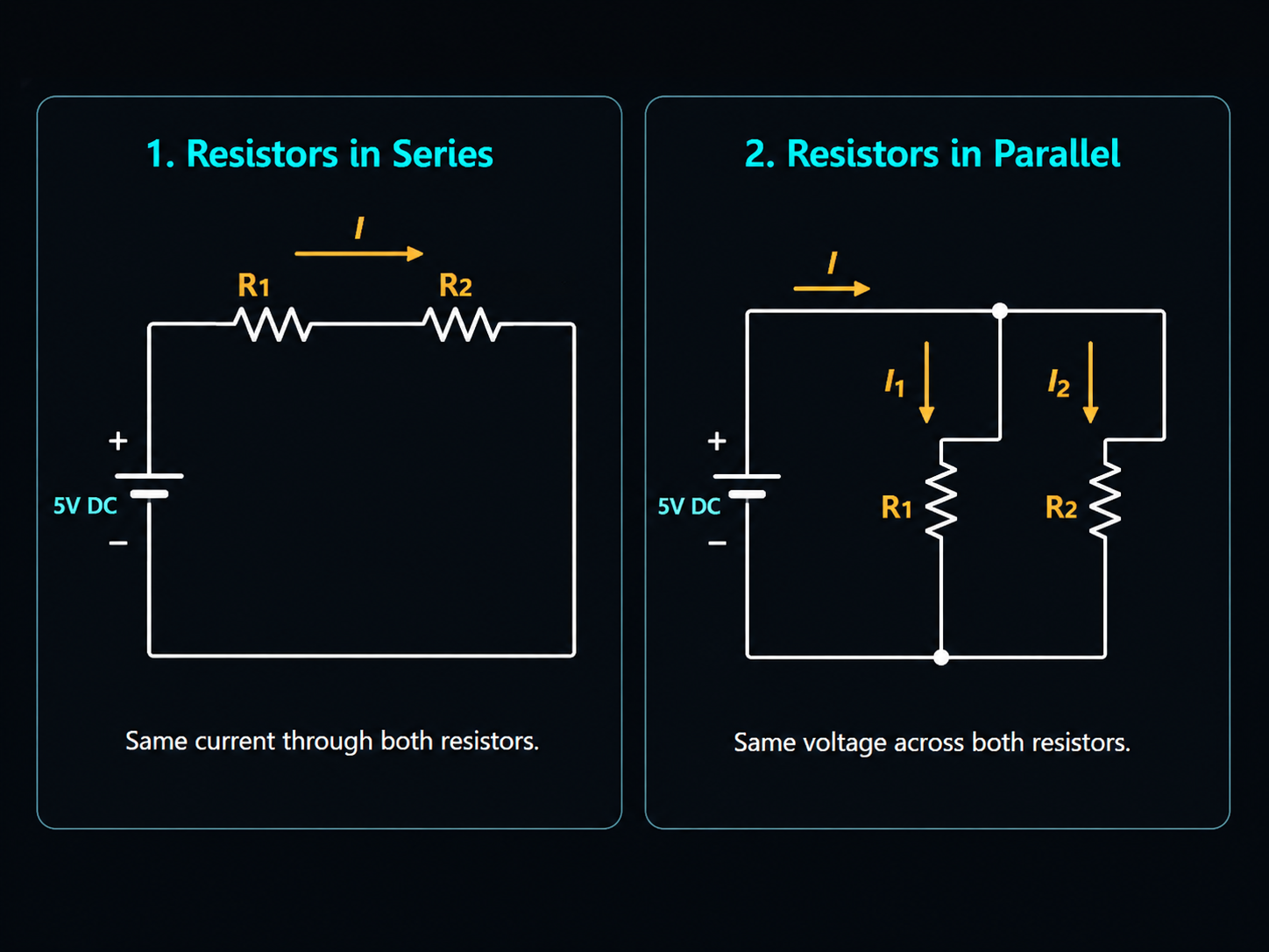
In a series connection:
- the same current flows through each resistor
- the voltage is divided across the resistors
- the total resistance increases
The equivalent resistance is:
For example, if:
and
then:
So two resistors in series behave like one larger resistor.
Resistors in Parallel
Two resistors are in parallel when both ends of the resistors are connected to the same two nodes. In a parallel connection:
- the voltage across each resistor is the same
- the current splits between the branches
- the total resistance becomes smaller
The equivalent resistance is:
For two resistors, this can also be written as:
For example, if:
and
then:
So two identical resistors in parallel behave like one resistor with half the resistance.
Important Comparison
This is where mechanical intuition is useful.
For two identical springs in parallel:
The system becomes stiffer.
For two identical resistors in parallel:
The system becomes less resistive.
At first, this may look opposite, but the idea is similar:
Adding more parallel paths makes it easier for the system to respond.
For springs, more parallel paths make it harder to stretch the system, so stiffness increases.
For resistors, more parallel paths make it easier for current to flow, so resistance decreases.
Quick Summary
| Connection Type | Mechanical Example | Electrical Example |
|---|---|---|
| Series | Springs connected end to end | Resistors connected one after another |
| Parallel | Springs connected side by side | Resistors connected across the same two nodes |
| Equivalent idea | Replace multiple elements with one equivalent stiffness | Replace multiple elements with one equivalent resistance |
For resistors:
| Connection | Equivalent Resistance |
|---|---|
| Series | R_eq = R_1 + R_2 |
| Parallel | 1/R_eq = 1/R_1 + 1/R_2 |
Understanding series and parallel connections is one of the most important first steps in reading circuits.